Real-Time Vehicle Control Systems
Our vehicles are becoming more and more computer systems, computer systems with wheels, wings, propellors, and many variations such as caterpillar tracks.
Real-time vehicle control and monitoring is an important and complex scenario for advanced C++ development. In this scenario software has to be developed that can be entrusted with the well-being of the vehicle’s crew and passengers. In this scenario, we examine what libraries might prove to be valuable building blocks, what kind of architecture and control flow might be involved, and best-practices for safe systems.
With this high-tech control system in mind, let’s examine the role individual Boost libraries might play.
Libraries
| Lbrary | Possible role in the tractor |
|---|---|
Real-time-ish I/O, CAN adapters, Ethernet, serial devices, timers |
|
Lock-free/shared state between control threads |
|
Sensor/command queues between acquisition and control threads |
|
Worker threads and synchronization |
|
Precise timing and control-loop periods |
|
Prevent mixing meters, feet, radians, PSI, kPa, etc. |
|
Simulating vehicle dynamics and hydraulic/engine systems |
|
Filters, interpolation, statistics, numerical functions |
|
Vehicle position, heading, paths and spatial calculations |
|
Recent sensor history / moving windows |
|
Efficiently indexing large collections of sensor/device data |
|
Diagnostics and event logging |
|
Diagnostic information after failures |
|
Portable error handling |
|
Configuration/calibration parameters |
|
Configuration and diagnostic interfaces |
|
Saving/restoring configuration or state |
|
Vehicle operating modes and state machines |
|
High-performance state-machine implementation, if appropriate |
|
Detecting arithmetic errors in safety-sensitive calculations |
|
Automated testing of control algorithms |
Architecture
As an example, we will look at a work-horse vehicle, the caterpillar tractor. The following image shows how much a modern interface might influence the design of the interior of the cab:
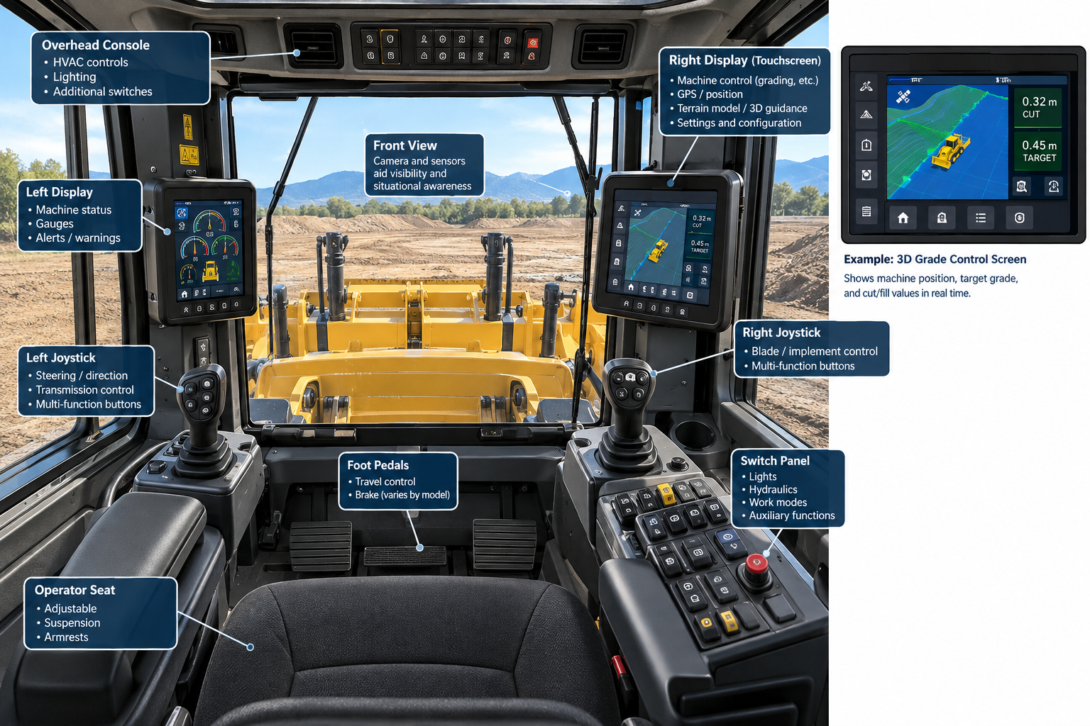
The basic architecture of a vehicle control app could be as simple as:
              every 10 ms

                  ┌───────────────┐
                  │ Read sensors  │
                  └───────┬───────┘
                          │
                          ▼
                  ┌───────────────┐
                  │ Validate data │
                  └───────┬───────┘
                          │
                          ▼
                  ┌───────────────┐
                  │ Update state  │
                  └───────┬───────┘
                          │
                          ▼
                  ┌───────────────┐
                  │ Control law   │
                  │ PID / model   │
                  └───────┬───────┘
                          │
                          ▼
                  ┌───────────────┐
                  │ Send commands │
                  └───────┬───────┘
                          │
                          ▼
            wait until next 10 ms starts
PID stands for Proportional-Integral-Derivative. It is one of the most common feedback-control algorithms used in engineering. (1)
Simulate a PID Controller
Let’s build a small, runnable vehicle speed-control simulation, showing the PID approach in action.
We’ll model a vehicle that must accelerate to a target speed and maintain it, even when a hill introduces extra resistance. A PID controller adjusts the throttle, while we simulate the vehicle’s motion over time.
The example demonstrate a useful separation of responsibilities:
-
Boost.Numeric/odeint : integrates the vehicle’s equations of motion.
-
Boost.Atomic : safely publishes the target speed between a simulated supervisory controller and the control loop.
#include <boost/atomic.hpp>
#include <boost/numeric/odeint.hpp>
#include <iostream>

// State variables: position (m), speed (m/s).
using State = std::array<double, 2>;
using namespace boost::numeric::odeint;

// Simplified vehicle parameters.
constexpr double mass = 1500.0;          // Kg
constexpr double max_force = 5000.0;     // Newtons
constexpr double rolling_force = 180.0;  // Newtons
constexpr double drag_factor = 0.42;     // Newtons / (meters/second)^2
constexpr double gravity = 9.81;         // meters/second^2

// PID controller: output is throttle in the range [0 = none, 1 = max].
struct PID
{
    double kp = 0.025;
    double ki = 0.003;
    double kd = 0.002;

    double integral = 0.0;
    double previous_error = 0.0;

    double update(double target, double speed, double dt)
    {
        const double error = target - speed;

        // Limit the integral term to reduce integral windup.
        integral = std::clamp(integral + error * dt,
            -20.0, 20.0);

        const double derivative = (error - previous_error) / dt;
        previous_error = error;

        const double output =
            kp * error + ki * integral + kd * derivative;

        return std::clamp(output, 0.0, 1.0);
    }
};

// Vehicle equations of motion.
// The throttle and road slope remain constant during each step.
struct VehicleDynamics
{
    double throttle;
    double slope;

    void operator()(const State& x, State& dxdt, double /* time */) const
    {
        const double speed = x[1];

        const double traction = throttle * max_force;
        const double drag = drag_factor * speed * std::abs(speed);
        const double rolling = rolling_force * std::tanh(speed / 0.2);

        // Convert road slope (rise / horizontal distance) to
        // the component of gravity acting along the road.
        const double hill_force =
            mass * gravity * slope /
            std::sqrt(1.0 + slope * slope);

        const double acceleration =
            (traction - drag - rolling - hill_force) / mass;

        dxdt[0] = speed;         // Position derivative.
        dxdt[1] = acceleration;  // Speed derivative.
    }
};

int main()
{
    constexpr double dt = 0.01;       // 100 Hz control rate.
    constexpr int total_steps = 3000; // 30 simulated seconds.

    // Shared target speed, in metres per second.
    // Another thread could safely update this atomic value.
    boost::atomic<double> target_speed_mps{ 25.0 };

    PID pid;
    State vehicle{ 0.0, 0.0 }; // Initial position and speed.
    runge_kutta4<State> integrator;

    // Print an aligned telemetry table.
    std::cout << std::left
        << std::setw(10) << "Time (s)"
        << std::right
        << std::setw(14) << "Target (m/s)"
        << std::setw(14) << "Speed (m/s)"
        << std::setw(16) << "Position (m)"
        << std::setw(12) << "Throttle"
        << '\n';

    std::cout << std::string(66, '-') << '\n';
    std::cout << std::fixed << std::setprecision(2);

    bool target_changed = false;

    for (int step = 0; step < total_steps; ++step)
    {
        const double t = step * dt;

        // At 20 seconds, reduce the target speed to 18 m/s.
        if (t >= 20.0 && !target_changed)
        {
            target_speed_mps.store(
                18.0, boost::memory_order_relaxed);
            target_changed = true;
        }

        const double target =
            target_speed_mps.load(boost::memory_order_relaxed);

        // Compute throttle from the current speed error.
        const double throttle = pid.update(target, vehicle[1], dt);

        // Simulate a gradient section from 8 to 16 seconds.
        const double slope = (t >= 8.0 && t < 16.0) ? 0.3 : 0.0;

        // Integrate vehicle position and speed by one time step.
        VehicleDynamics dynamics{ throttle, slope };
        integrator.do_step(dynamics, vehicle, t, dt);

        // Display telemetry once per simulated second.
        if (step % 100 == 0)
        {
            std::cout << std::left
                << std::setw(10) << t
                << std::right
                << std::setw(14) << target
                << std::setw(14) << vehicle[1]
                << std::setw(16) << vehicle[0]
                << std::setw(12) << throttle
                << '\n';
        }
    }

    return 0;
}
Build with a C++17-capable compiler.
What to look for in the results:
-
From 0 to 8 seconds, throttle increases the vehicle’s speed toward 25 m/s.
-
From 8 to 16 seconds, uphill resistance increases, so the controller should maintain a higher throttle to compensate, though momentum is a factor.
-
At 20 seconds, the target drops to 18 m/s and there is no uphill. The controller reduces throttle, and the vehicle slows as drag and rolling resistance dissipate its momentum.
This is a simplified throttle-only controller, with no active braking, actuator delay, gear shifting, or traction limits.
Time (s)    Target (m/s)   Speed (m/s)    Position (m)    Throttle
------------------------------------------------------------------
0.00               25.00          0.03            0.00        1.00
1.00               25.00          2.03            1.03        0.63
2.00               25.00          3.93            4.02        0.58
3.00               25.00          5.67            8.83        0.54
4.00               25.00          7.27           15.31        0.50
5.00               25.00          8.74           23.33        0.46
6.00               25.00         10.08           32.75        0.43
7.00               25.00         11.32           43.46        0.40
8.00               25.00         12.41           55.34        0.37
9.00               25.00         10.77           66.92        0.42
10.00              25.00          9.26           76.92        0.46
11.00              25.00          7.88           85.48        0.49
12.00              25.00          6.61           92.72        0.52
13.00              25.00          5.45           98.74        0.55
14.00              25.00          4.39          103.65        0.58
15.00              25.00          3.41          107.54        0.60
16.00              25.00          2.54          110.50        0.62
17.00              25.00          4.40          113.98        0.57
18.00              25.00          6.10          119.24        0.53
19.00              25.00          7.67          126.14        0.49
20.00              18.00          9.09          134.53        0.00
21.00              18.00          9.85          144.01        0.26
22.00              18.00         10.55          154.21        0.25
23.00              18.00         11.18          165.08        0.23
24.00              18.00         11.77          176.56        0.21
25.00              18.00         12.30          188.59        0.20
26.00              18.00         12.79          201.14        0.19
27.00              18.00         13.23          214.15        0.18
28.00              18.00         13.64          227.59        0.17
29.00              18.00         14.01          241.42        0.16
Now, find the line:
const double slope = (t >= 8.0 && t < 16.0) ? 0.3 : 0.0;
and change it to:
const double slope = (t >= 8.0 && t < 16.0) ? -0.1 : 0.0;
A downhill slope. Now we are going to see why brakes are necessary:
Time (s)    Target (m/s)   Speed (m/s)    Position (m)    Throttle
------------------------------------------------------------------
0.00               25.00          0.03            0.00        1.00
1.00               25.00          2.03            1.03        0.63
2.00               25.00          3.93            4.02        0.58
3.00               25.00          5.67            8.83        0.54
4.00               25.00          7.27           15.31        0.50
5.00               25.00          8.74           23.33        0.46
6.00               25.00         10.08           32.75        0.43
7.00               25.00         11.32           43.46        0.40
8.00               25.00         12.45           55.34        0.37
9.00               25.00         14.41           68.79        0.32
10.00              25.00         16.19           84.10        0.28
11.00              25.00         17.82          101.12        0.24
12.00              25.00         19.31          119.70        0.20
13.00              25.00         20.66          139.70        0.17
14.00              25.00         21.89          160.99        0.14
15.00              25.00         23.01          183.45        0.11
16.00              25.00         24.02          206.98        0.08
17.00              25.00         24.02          231.00        0.08
18.00              25.00         24.02          255.01        0.08
19.00              25.00         24.02          279.03        0.08
20.00              18.00         24.02          303.05        0.00
21.00              18.00         23.74          326.93        0.00
22.00              18.00         23.46          350.53        0.00
23.00              18.00         23.19          373.86        0.00
24.00              18.00         22.92          396.91        0.00
25.00              18.00         22.66          419.70        0.00
26.00              18.00         22.39          442.22        0.00
27.00              18.00         22.13          464.49        0.00
28.00              18.00         21.88          486.49        0.00
29.00 18.00 21.63 508.24 0.00- Note
-
Check out the foot-off-the-throttle situation for the last 9 seconds!
Next Steps
A natural next step would be to add Boost.Units for dimensional checking and Boost.Statechart or Boost.Msm to model vehicle modes such as Cruising, HillClimb, Braking, and EmergencyStop.
Footnotes
(1) In the tractor example, “Control law — PID/model” means that the software controlling things such as hydraulic valves, blade position, engine speed, or vehicle speed could use either a PID controller, a model-based controller, or a combination of the two. Suppose the tractor’s blade is supposed to be at a particular height. The controller continuously compares desired blade height against actual blade height, the delta being treated as an error. A PID controller uses that error in three ways:
| Part | Meaning | Intuition |
|---|---|---|
P |
Proportional |
“How far away am I right now?” |
I |
Integral |
“How long have I been wrong?” |
D |
Derivative |
“How quickly am I approaching the target?” |
The P component might say: "We’re 10 cm low, so raise the blade substantially" and as the blade gets closer: "We’re only 2 cm low, so raise it much more gently". The I component notices if, for example, the blade consistently stays 1 cm below the target because of hydraulic leakage or load. The D component notices that the blade is moving rapidly toward the target and reduces the command - to help prevent overshooting.